


Introduction
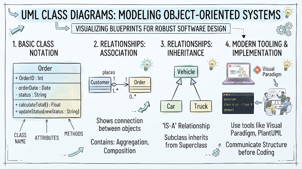
In the world of Object-Oriented Design (OOD), the class is the fundamental building block. While objects are the running instances that execute our applications, classes are the blueprints that define their structure and behavior. Understanding how to model these classes effectively is crucial for creating robust, maintainable software systems.
Unified Modeling Language (UML) Class Diagrams provide a standardized visual language for describing these blueprints. They allow developers, architects, and stakeholders to communicate complex system structures clearly before a single line of code is written. This guide explores the core concepts of UML class diagrams, detailing everything from basic notation to complex relationships, and demonstrates how to implement them using modern tooling like Visual Paradigm and PlantUML.
Key Concepts
1. The Class Structure
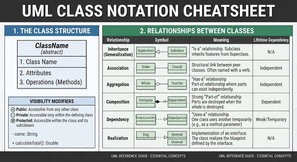
A class in UML is represented as a rectangle divided into three compartments:
-
Class Name: The top partition contains the name of the class. Abstract classes are typically denoted by italics.
-
Attributes: The middle partition lists the state or data members of the class. Each attribute has a name and a type (e.g.,
name: String). -
Operations (Methods): The bottom partition lists the behaviors or services the class provides. Methods include a signature and a return type (e.g.,
calculateTotal(): Double).
Visibility Modifiers:
-
+Public: Accessible from any other class. -
-Private: Accessible only within the defining class. -
#Protected: Accessible within the class and its subclasses.
2. Relationships Between Classes
UML defines several specific ways classes can interact. Understanding the semantic difference between these is vital for accurate modeling.
| Relationship | Symbol | Meaning | Lifetime Dependency |
|---|---|---|---|
| Inheritance (Generalization) | Solid line, hollow arrowhead | “Is-a” relationship. Subclass inherits features from Superclass. | N/A |
| Association | Solid line | Structural link between peer classes. Often named with a verb. | Independent |
| Aggregation | Solid line, unfilled diamond | “Has-a” relationship. Part-of relationship where parts can exist independently. | Independent |
| Composition | Solid line, filled diamond | Strong “Part-of” relationship. Parts are destroyed when the whole is destroyed. | Dependent |
| Dependency | Dashed line, open arrow | “Uses-a” relationship. One class uses another temporarily (e.g., as a method parameter). | Weak/Temporary |
| Realization | Dashed line, hollow arrowhead | Implementation of an interface. The class realizes the blueprint defined by the interface. | N/A |
3. Perspectives of Class Diagrams
The level of detail in a diagram depends on the development phase:
-
Conceptual: Focuses on domain concepts and vocabulary. Minimal technical detail.
-
Specification: Focuses on interfaces and Abstract Data Types (ADTs). Defines what the system does, not how.
-
Implementation: Describes exactly how classes will be coded, including specific data types and visibility modifiers.
Tooling: Visual Paradigm + AI + VPasCode Editor
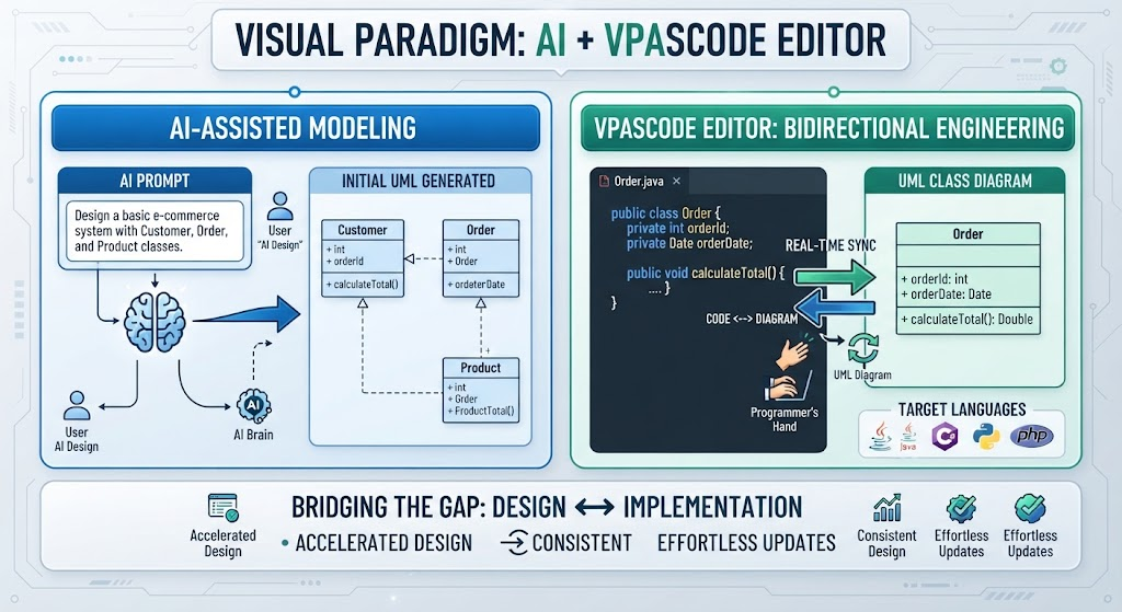
Modern modeling tools have evolved beyond simple drag-and-drop interfaces. Visual Paradigm integrates AI assistance and code-engineering capabilities to bridge the gap between design and implementation.
-
AI-Assisted Modeling: Use natural language prompts to generate initial class structures or suggest relationships based on domain descriptions.
-
VPasCode Editor: This feature allows for bidirectional engineering. You can write code in the editor and see the UML diagram update in real-time, or modify the diagram and have the tool scaffold the corresponding class files in your target programming language (Java, C#, Python, etc.).
Class Diagram Examples Rendered in VPasCode
PlantUML is a popular text-based tool for creating UML diagrams. Below are renderable examples demonstrating the concepts discussed above.
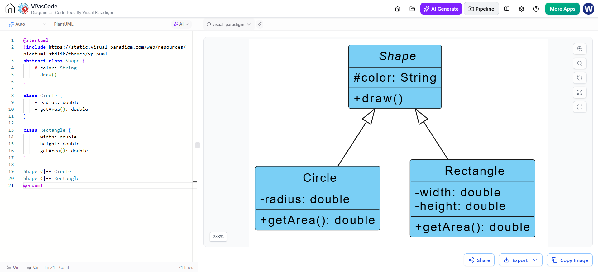
Example 1: Basic Class and Inheritance
This example shows a Shape superclass and two subclasses, demonstrating the “is-a” relationship.
@startuml
abstract class Shape {
    # color: String
    + draw()
}

class Circle {
    - radius: double
    + getArea(): double
}

class Rectangle {
    - width: double
    - height: double
    + getArea(): double
}

Shape <|-- Circle
Shape <|-- Rectangle
@enduml
Example 2: Aggregation vs. Composition
This example distinguishes between a University (which has Departments that might survive the university’s closure in some models, but here we’ll use Composition for strong ownership) and a Department having Professors (Aggregation, as professors can move between departments).
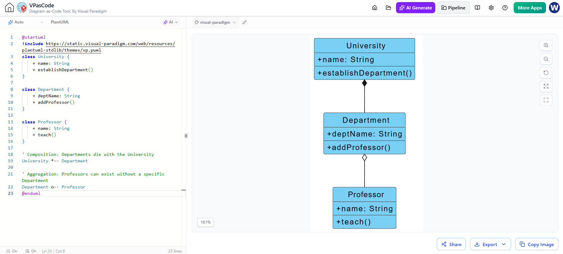
@startuml
class University {
    + name: String
    + establishDepartment()
}

class Department {
    + deptName: String
    + addProfessor()
}

class Professor {
    + name: String
    + teach()
}

' Composition: Departments die with the University
University *-- Department

' Aggregation: Professors can exist without a specific Department
Department o-- Professor
@enduml
Example 3: Dependency and Realization
This example shows a Person who depends on a Book to perform a hasRead check, and a PremiumMember who realizes the IMembership interface.
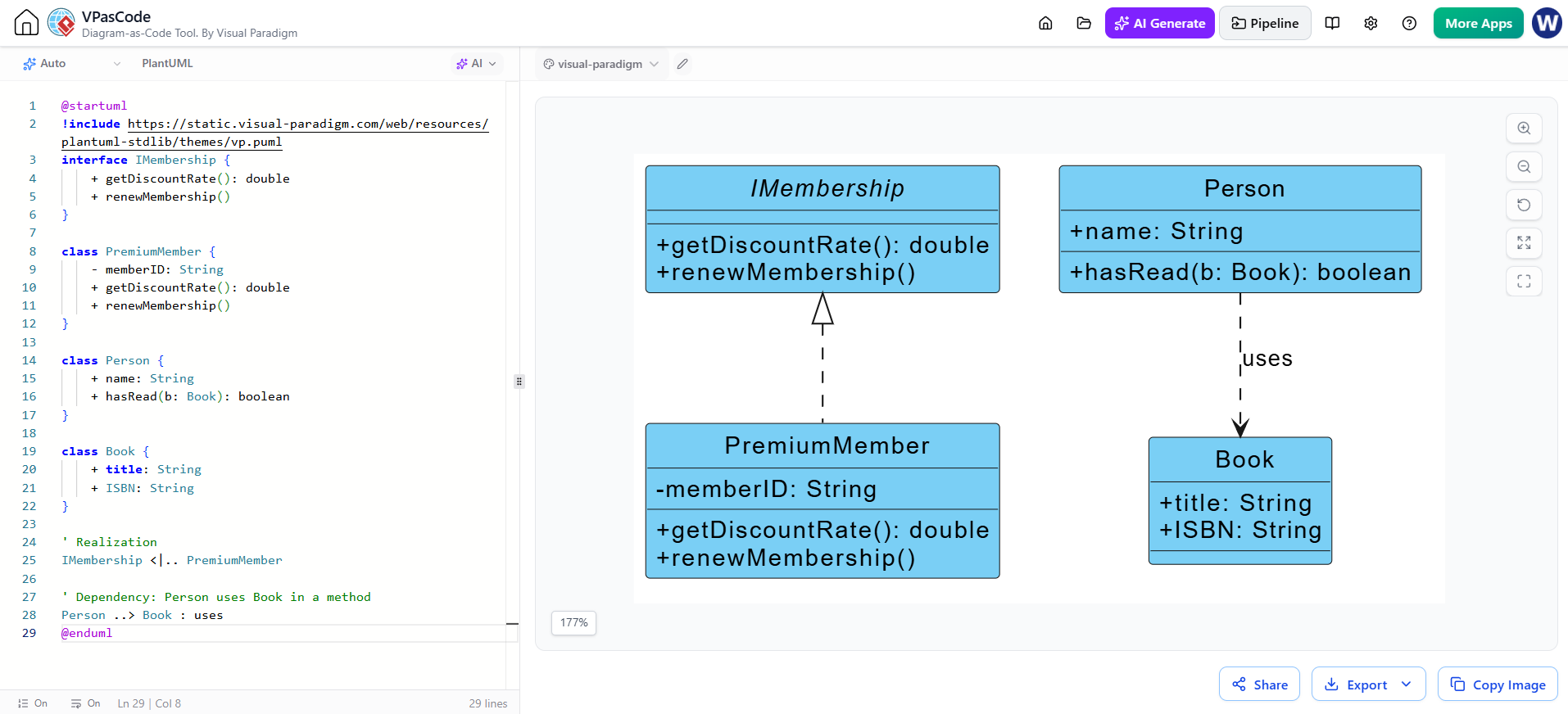
@startuml
interface IMembership {
    + getDiscountRate(): double
    + renewMembership()
}

class PremiumMember {
    - memberID: String
    + getDiscountRate(): double
    + renewMembership()
}

class Person {
    + name: String
    + hasRead(b: Book): boolean
}

class Book {
    + title: String
    + ISBN: String
}

' Realization
IMembership <|.. PremiumMember

' Dependency: Person uses Book in a method
Person ..> Book : uses
@enduml
Example 4: Complete Order System
A more complex example showing associations, cardinality, and multiple relationship types.
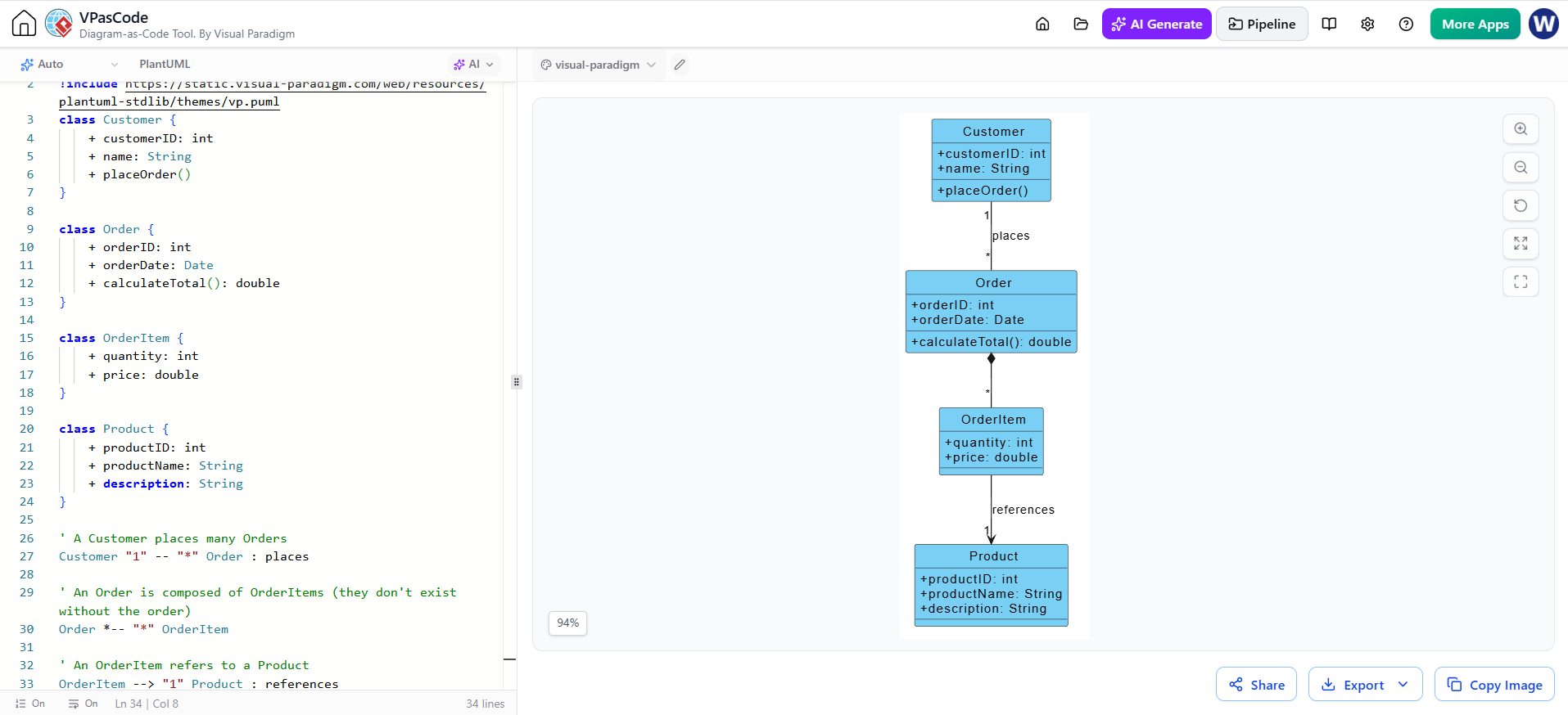
@startuml
class Customer {
    + customerID: int
    + name: String
    + placeOrder()
}

class Order {
    + orderID: int
    + orderDate: Date
    + calculateTotal(): double
}

class OrderItem {
    + quantity: int
    + price: double
}

class Product {
    + productID: int
    + productName: String
    + description: String
}

' A Customer places many Orders
Customer "1" -- "*" Order : places

' An Order is composed of OrderItems (they don't exist without the order)
Order *-- "*" OrderItem

' An OrderItem refers to a Product
OrderItem --> "1" Product : references
@enduml
Conclusion
UML Class Diagrams are more than just documentation; they are a critical thinking tool for software design. By mastering the notation for classes, attributes, and operations, and by understanding the nuanced differences between inheritance, aggregation, composition, and dependency, you can create models that accurately reflect your system’s architecture.
Leveraging tools like Visual Paradigm and PlantUML allows you to iterate quickly on these designs. Whether you are starting with a conceptual domain model or finalizing an implementation-ready specification, clear class diagrams ensure that your team shares a common understanding of the system’s structure, leading to higher quality code and fewer architectural surprises down the road.
References
-
Visual Paradigm Community Edition: Enterprise-Grade UML Modeling, Free Forever: Official announcement of the free Community Edition, highlighting its full UML 2.x support, model-view consistency, and real-time syntax checking for non-commercial use.
-
How to draw a Sequence Diagram in UML – Visual Paradigm: A practical step-by-step tutorial on creating sequence diagrams, covering lifelines, messages, combined fragments, and productivity features like the Resource Catalog and Sweeper/Magnet tools.
-
Enhancing UML with Visual Paradigm Tools: A guide on extending UML’s value through code generation and synchronization, linking UML with requirements/ERD/BPMN, version control, and AI-driven automation for team collaboration.
-
UML Documentation: Create Client-Facing Reports: Explains how to use Visual Paradigm’s Doc Composer to transform raw UML models into polished, audience-specific reports for executives, product managers, and developers.
-
From Whiteboard to Diagram: Turning Ideas into Clear Models: Focuses on practical UML modeling techniques, choosing the right diagram type, and leveraging Visual Paradigm’s templates to accelerate the diagramming process.
-
Comprehensive Reporting and Documentation: Details the final phase of the use case lifecycle, focusing on AI-powered reporting that generates executive summaries, developer guides, and QA audit trails from model elements.